SCPC/MCPC Digital Audio Receiver
for Satellite Based Digital Broadcast Systems
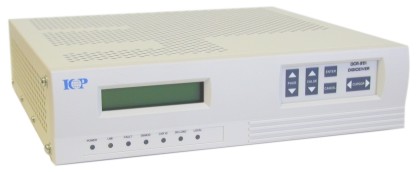
Model DCR-981 DigiCeiver
ICP's new DCR-981 DigiCeiver® is the only Single Channel Per Carrier (SCPC) audio receiver that can also be utilized in a Multi Channel Per Carrier (MCPC) mode. Specifically designed for expanding existing SCPC networks, the DCR-981 is compatible with other manufacturers' networks. Its unique capability for MCPC mode, makes meeting future network demands for MCPC operation possible without changing receivers.
Features
- Economical Receiver For Expansion of Existing or New SCPC Networks
- SCPC, MPEG Layer 2, Digital Audio Receiver
- BPSK or QPSK Operation
- 64 to 384 kbps Audio Channel Data Rates in SCPC Mode
- Downloadable Software Over the Network
- Ancillary Data Up to 19.2 kbps
- 4 Relay Closures
- In-Band Network Control Signaling
- Expandable to MCPC Audio Operation with aggregate data rates up to 4.096 Mbps
- Backwards Compatible with ICP DCR-972 and DCR-974 MCPC Networks
Introduction
The Model DCR-981 DigiCeiver® is an economical, all digital audio receiver intended for use in satellite based broadcast systems. Its many applications include radio program distribution to network affiliates and music distribution for corporate and retail applications. It is intended for use in many existing SCPC audio networks for network expansion and for new SCPC audio networks. It can also be used to expand ICP MCPC audio networks operating with or without our store and forward capability or expand SCPC networks to MCPC operation without changing receivers. The Model DCR-981 utilizes state-of-the-art digital technology, which allows a wide degree of flexibility to the user through the in-band network configuration and control capability.
The DCR-981 is an Single Channel Per Carrier (SCPC) receiver with a ISO/MPEG Layer 2 decoder providing two audio outputs, four relay closures, and one ancillary data stream up to 19.2 kbps. The MPEG decoder is capable of delivering either one stereo or two mono outputs from a non-multiplexed digital source. It provides BPSK or QPSK operation at data rates of 64 kilobits per second (kbps) up to 384 kbps. Network control and configuration commands are multiplexed into the ancillary data channel along with relay closure information and user data, as part of the transmitted signal. This allows convenient control of all network receivers from the head-end.
A high performance sequential Forward Error Correction (FEC) decoder provides outstanding bit error rate (BER) performance. A Viterbi FEC decoder is also available. The DCR-981 is fully compatible with existing BPSK and QPSK, rate 1/2 coded digital signals currently transmitted by many service providers. Open network standards are followed for differential encoding, scrambling, forward error correction and signal spectral shaping to allow use in many existing open networks.
The ICP Network Control System (NCS) provides a greater degree of flexibility for network configuration but is not required for SCPC operation. When used, the NCS can configure Center Frequency, Carrier ID, Mode of Operation, Data Rate, Sweep Limit, and Error Rate Test Length from the head end or through the rear panel Remote connector on the receiver. They can also be entered locally through the front panel controls and display.
The DCR-981 is available in a desk top chassis design or with an optional rack mount. The desktop chassis measures 12"W x 8"L x 3"H and weighs less than 5.5 lbs (2.5 Kg)
An internal, universal input, switching power supply provides operation from 90 VAC to 260 VAC, 47 Hz to 63 Hz.
DCR-981 SPECIFICATIONS
Receiver Characteristics
|
Input Frequency Range |
950-1450 MHz |
|
Input Connector |
Type "F" female, 75 Ohms |
|
Carrier Frequency Tuning |
Synthesized in 0.10 MHz steps from 950 MHz to 1450 MHz |
|
PSK mode |
BPSK or QPSK, programmable |
|
Data rate: |
64 kbps up to 384 kbps in BPSK or QPSK mode. Higher rates up to 4096 kbps in MCPC configurations |
|
Forward Error Correction |
Rate 1/2 sequential, 2 bits soft decisions or Viterbi K=7, 3 bit soft decision |
|
Acquisition sweep range |
Programmable in 10 kHz increments up to ± 2 MHz |
|
Bit Error Rate Performance |
Typically 10-7 at 5.5 dB Eb/No |
|
User Data Output Electrical Interface: |
EIA RS-232 |
|
Configuration Storage: |
Non-volatile |
|
Software Downloadability |
All operating software is downloadable |
Audio Characteristics
|
Audio algorithms |
MPEG layer 2 |
|
Audio data rates |
64, 128, 192, 256, 320, 384 kbps |
|
Audio modes |
Mono, dual mono, stereo, and joint stereo |
|
Peak output level |
+18 dBu |
|
Signal to noise ratio |
85dB (A weighted), optional 95dB (A weighted) |
|
Audio bandwidth |
20 Hz to 7.5,11,14.5,or 20 kHz depending on mode |
|
Audio response |
Typically ±0.3 dB |
|
Analog output interface |
Electronically balanced, differential, analog output |
|
Output impedance |
Typically 50 ohms (differential) |
|
User Ancillary data |
Async data from 300 baud to 19.2 kbps |
|
Software Downloadability |
All operating software is downloadable |
Control and Display Functions
|
Controllable parameters |
LNB Band, Carrier Frequency, Carrier ID, BPSK/QPSK Mode, Data Rate, Sweep Width, Local or Remote Control, Signal Strength (Eb/No) Display, Symbol Error Rate Display. |
|
Indicators |
LED's Indicate: Power, LNB Fault, Summary Fault, Demodulator Lock, Carrier ID, Download, Local Control |
| Network Control Channel | Provides synchronization, carrier identification and control of the receivers operating parameters |
| Addressability | Each receiver is individually addressable. Addresses may be global or individual |
Power/Physical/Environmental
|
LNB Power |
+20 V nominal at up to 0.4 A. separately fused and surge protected |
|
AC Power |
Universal input, 90 VAC to 260 VAC, 47 Hz to 63 Hz, less than 50 watts |
| Chassis type | Desktop chassis or standard 19" EIA rack mount kit (optional) |
| Size | 3" high, 12" wide, 8" deep all metal chassis |
| Weight | Less than 5.5 lbs. (2.5 Kg) |
|
Ancillary Data Output Connector |
9 pin Type "D" connector female |
| Relay Closures | 25 pin Type "D" connector female |
| Network Control | 9 pin Type "D" connector female |
| Audio Output Connector | 9 pin Type "D" connector male |
| Temperature | 0° C to +50° C operating temperature |
| Humidity | 0 to 100% non condensing |